Thursday, February 5, 2015

How to Weld Underwater

Underwater welding is a process whereby metals are melted together underwater to either repair a structure or create a new structure. Used on oil wells, ships, and other underwater structures, underwater welding is done by one of two methods. The first is hyperbaric welding, in which a structure is created around the weld and a pressurized environment created. The second is arc welding, in which the welding electrode contains a flux coating that releases gases to preserve the integrity of the weld. Because of the dangers of shock, explosion and poisoning, underwater welding is only performed by professionals with both diving and welding certifications.

Hyperbaric Welding Method
  1. Identify the site and material of the joint to be welded as most underwater welds involve steel, but metals may vary.

  2. Prepare a chamber to place around the joint (each joint should have a separate chamber).

  3. Introduce gas into the chamber.
    A typical gas mixture uses helium and oxygen, but requirements vary based on the specific joint to be welded. The pressure of the chamber should be slightly above that of the surrounding water.

  4. Run a power supply to the chamber and set up a port for your electrodes.
    Multiple electrodes will likely be required, and should be placed in advance in front of the area of the joint to be welded.

  5. Dive to the weld site.

  6. Turn on the power supply and weld the joint from outside the chamber.

  7. Turn off the power supply as soon as the welding is done.


Arc Welding Method
  1. Investigate the joint to be welded and identify the types of metals involved.

  2. Prepare the adequate electrodes, plan out the order of welding and dive to the weld site.

  3. Weld the joint, ensuring that the flux coating of the weld is coming off as expected, and that too much hydrogen is not approaching the joint.

  4. Turn off the power supply as soon as the welding is done.

Source :
http://www.wikihow.com/Weld-Underwater

Subsea Tie-in Systems

SUBSEA TIE-IN SYSTEM

Subsea flowlines are used for the transportation of crude oil and gas from subsea wells, manifolds, off-shore process facilities, loading buoys, S2B (subsea to beach), as well as re-injection of water and gas into the reservoir. Achieving successful tie-in and connection of subsea flowlines is a vital part of a subsea field development.

Vertical Tie-in System
Vertical connections are installed directly onto the receiving hub in one operation during tie-in. Since the Vertical Connection System does not require a pull-in capability, it simplifis the tool functions, provides a time effiient tie-in operation and reduce the length of Rigid Spools.
Stroking and connection is carried out by the the Connector itself, or by the ROV operated Connector Actuation Tool (CAT) System.

Vertical Tie-in assisted by V-CAT
Horizontal Tie-in System
Horizontal Tie-in may be used for both first-end and second-end tie-in of both flowlines, umbilicals and Jumper spools. The termination head is hauled in to the Tie-in point by use of a subsea winch. Horizontal Tie-in may be made up by Clamp Connectors operated from a Tie-in tool, by integrated hydraulic connectors operated through the ROV, or by non-hydraulic collect connectors with assistance from a Connector Actuation Tool (CAT) and ROV. Horizontal connections leave the flowline/ umbilical in a straight line, and is easy to protect if overtrawling from fishermen should occur.

Horizontal Tie-in


Considerations related to choice of connector can be seen in the table below


Connector

  • Collect connector
    Collet connectors consist of collet-style “figer” design which fimly locks around a mating hub. Collet connectors are used for both vertical and horizontal jumper spool connections and are available in both integral hydraulic and mechanical (with separate actuation tool) confiurations.

    Collect connector
  • Clamp connector
    Clamp connectors consist of a two piece segmented clamp design and are particularly well suited for larger bore, lower pressure horizontal connection applications.
    Clamp connector

  • Bolted flange
    A bolted flange connection utilizes a metal gasket which is compressed to seal between two flanges. The bolts axis has the same orientation as the pipeline. When the bolts are tightened the metal gasket is deformed between the two flanges. The gasket allows the flanged connection to have some initial misalignment, but it is very vulnerable to rotational misalignment about z-axis due to the 
    flanges respective bolt hole orientation.

    Bolted flange

Source :
Sletteb, Espen, 2012, Master's Thesis : Tie-in SPools - A Verification Study, University of Stavanger
Subsea Tie-in System brochure by FMC Technologies

Wednesday, February 4, 2015

Horizontal Directional Drilling

Didalam melakukan pengeboran suatu formasi, selalu diharapkan pengeboran dengan lubang yang lurus/vertikal, karena pengeboran dengan lubang yang lurus/vertikal selain dalam operasinya lebih mudah, juga pada umumnya biayanya menjadi lebih murah. Namun karena kondisi-kondisi tertentu, pengeboran lurus/vertikal tidak bisa dilakukan oleh karenanya perlu dilakukan pengeboran yang bisa diarahkan sesuai kondisi-kondisi tersebut. Pengeboran yang dilakukan dengan cara mengarahkan lubang biasa disebut dengan pengeboran berarah atau pengeboran horisontal (Directional and Horizontal Drilling). Beberapa faktor-faktor penyebab dilakukannya pengeboran berarah atau horizontal (Directional and Horizontal Drilling) adalah geografi, geologi dan pertimbangan ekonomi. Di bawah ini beberapa contoh alasan dilakukannya pengeboran berarah atau horizontal (Directional and Horizontal Drilling).

  1. Inaccesible Location Drilling
    Beberapa reservoir dengan kondisi di permukaan yang tidak memungkinkan untuk dilakukan pengeboran lurus/vertical akan sangat cocok untuk dilakukan pengeboran berarah atau horizontal (Directional and Horizontal Drilling). Teknik ini adalah salah satu dari teknik pengeboran berarah yang paling umum dilakukan untuk mencapai lapisan yang tidak dapat dicapai dengan cara yang biasa, sebagai contoh reservoir yang terletak di bawah kota, di bawah lahan pertanian/perkebunan, dll. Gambar dibawah memperlihatkan formasi yang berada di bawah perkotaan sehingga dilakukan pengeboran berarah atau horizontal (Directional and Horizontal Drilling).

  2. Multiple Well DrillingBila suatu lokasi pengeboran memiliki keterbatasan area pada permukaan sehingga tidak mungkin dilakukan pengeboran banyak sumur dengan letak yang berbeda. Hal ini bisa diatasi dengan melakukan pengeboran multiple well. Yakni mengebor pada satu lokasi dengan banyak sumur yang dibuat, untuk itu dilakukanlah pengeboran berarah atau horizontal (Directional and Horizontal Drilling). Multiple well drilling ini sering dilakukan pada pengeboran lepas pantai dari suatu platform tunggal atau dari suatu tempat yang terpencil. Gambar dibawah  memperlihatkan suatu platform yang melakukan Multiple well drilling.

  3. Salt Dome DrillingPada daerah yang didapati kubah garam (salt dome) yang letaknya berada di atas reservoir minyak, pengeboran lurus/vertical tidak mungkin dilakukan. Karena bila pengeboran menembus kubah garam (salt dome) akan mengakibatkan masalah yang serius terutama akan terjadinya blow out sehingga perlu dilakukan pengeboran berarah atau horizontal (Directional and Horizontal Drilling) yangakan mengarah langsung ke reservoir minyak. Gambar dibawah memperlihatkan reservoir yang berada di bawah kubah garam (salt dome).

  4.  Side Tracking atau Straightening
    Kadangkala dalam melakukan operasi pengeboran lurus/vertikal terjadi pembelokan yang sangat parah sehingga menjauh dari target, sehingga perlu untuk meluruskan kembali lubang sumur tersebut.
    Untuk itu dilakukan side tracking dengan melakukan pengeburan berarah. Atau pada kejadian dimana fish yang tidak dapat diangkat dan terkubur dilubang bor, pengeboran harus menghindari fish tersebut agar peralatan pengeboran tidak rusak maka dilakukan side tracking.
  5. Relief Well DrillingPada kejadian sumur yang blow out, salah satu cara untuk menanggulanginya adalah dengan mengebor atau membuat relief well. Relief well merupakan sumur yang dibuat di dekat sumur yang blow out dengan tujuan untuk mengalirkan fluida yang mengakibatkan blow out sehingga dapat dikendalikan. Biasanya relief well dilakukan dengan pengeboran berarah atau horizontal (Directional and Horizontal Drilling).


Pemboran berarah dapat dikerjakan dengan peralatan membor konvensional, dimana pipa bor diputar dari permukaan untuk memutar mata bor di bawah. Kelemahannya, sudut yang dapat dibentuk sangat terbatas. Pemboran berarah sekarang lebih umum dilakukan dengan memakai motor berpenggerak lumpur (mud motor) yang akan memutar mata bor dan dipasang di ujung pipa pemboran. Seluruh pipa pemboran dari permukaan tidak perlu diputar, pipa pemboran lebih dapat “dilengkungkan” sehingga lubang sumur dapat lebih fleksibel untuk diarahkan.

Mud motor


Ilustrasi proses horizontal directional drilling dapat dilihat pada video berikut ini.
Referensi :

Dasar-Dasar Teknik Pengeboran (2013), Kementrian Pendidikan dan Kebudayaan Republik Indonesia

Pipeline Elbow

Elbows are categorized based on various design features as below:
  • Long Radius (LR) Elbows – radius is 1.5 times the pipe diameter
  • Short Radius (SR) Elbows – radius is 1.0 times the pipe diameter
  • 90 Degree Elbow – where change in direction required is 90°
  • 45 Degree Elbow – where change in direction required is 45°
image
90 degree Elbow Pipe
A 90 degree elbow is also called a “90 bend” or “90 ell”. It is a fitting which is bent in such a way to produce 90 degree change in the direction of flow in the pipe. It used to change the direction in piping and is also sometimes called a “quarter bend”. A 90 degree elbow attaches readily to plastic, copper, cast iron, steel and lead. It can also attach to rubber with stainless steel clamps. It is available in many materials like silicone, rubber compounds, galvanized steel, etc. The main application of an elbow (90 degree) is to connect hoses to valves, water pressure pumps, and deck drains. These elbows can be made from tough nylon material or NPT thread.
image
45 Degree Elbow Pipe
A 45 degree elbow is also called a “45 bend” or “45 ell”. It is commonly used in water supply facilities, food industrial pipeline networks, chemical industrial pipeline networks, electronic industrial pipeline networks, air conditioning facility pipeline, agriculture and garden production transporting system, pipeline network for solar energy facility, etc.
Most elbows are available in short radius or long radius variants. The short radius elbows have a center-to-end distance equal to the Nominal Pipe Size (NPS) in inches, while the long radius is 1.5 times the NPS in inches. Short elbows are widely available, and are typically used in pressurized systems.
Elbow Pipe having a lot of usage. One of the elbow usage in a pipe line is for determining the rate of flowing the pipe
INTRODUCTION THE USE OF AN ELBOW IN A PIPE LINE FOR DETERMINING THE RATE OF FLOWING THE PIPE
1. Object and Scope of Investigation.-The tests herein reporter were made for the purpose of obtaining information concerning the feasibility of using an elbow in a pipe line as a means of determiningthe flow of a fluid through the pipe, by measuring the difference between the pressures of the fluid on the inside and outside curves of theelbow, respectively, as indicated in Fig. 1. Some of the desirable characteristics of an elbow used as a flow meter are low initial cost, smallcost of upkeep, and no additional resistance to flow due to the elbowbeing converted into a meter.
There are very few published data’-9* available concerning elbowsused as flow meters, especially data concerning the ordinary commercial type of elbow.
The tests reported in this bulletin were made on threaded andflanged elbows of long and short radii, ranging in diameter from oneinch to twenty-four inches. Sixteen different elbows were tested innearly forty different positions and locations in various pipe lines. Allthe elbows tested were 90-deg. bends; typical elbows are shown inFig. 2. Water was the only fluid used in the tests of the elbow metersherein reported.
2. Acknowledgments.-The investigation reported in this bulletin was carried out in the Hydraulics Laboratory of the University ofIllinois as part of the work of the Engineering Experiment Station,of which DEAN M. L. ENGER is the director, and of the Department ofTheoretical and Applied Mechanics, of which PROF. F. B. SEELY isthe head.The tests on the 24-in. elbows were made by MR. E. C. CHAMBERLIN, JR., a senior student at the University of Illinois, in satisfyingthe requirement for a thesis for the degree of Bachelor of Science.
Reference :
Lanford, Wallace M. 1936. The Use Of An Elbow In A Pipe Line Fordetermining The Rate Of Flowin The Pipe. University Of Illinois Bulletin.

Pipeline Inspection

Pipeline inspection is part of pipeline integrity management for keeping the pipeline in good condition. The rules governing inspection are the pipeline safety regulation. In most cases, the pipeline is inspected regularly. 

The pipeline safety regulations require that the operator ensure that a pipeline is maintained in an efficient state, in efficient working order, and in good repair. In fact, the pipeline operator has a vested interest in the pipeline being operated effectively and safely to satisfy the appropriate authority and save the failure cost in environment, loss of production, and repair. The pipeline inspection includes external inspection and internal inspection. The subsea pipeline external inspection looks at the pipeline's external condition, such as concrete weight coating. trench and concrete mattress losses, marine growth, anode wastage, and corrosion, free span and global buckling condition, and damages due to external load through visual observation. The subsea pipeline internal inspection is normally carried out though nondestructive testing techniques and technologies by intelligent pigs, such as magnetic-flux leakage technology in axial and circumferential conditions, ultrasound technologies, eddy-current technologies, and other technologies. 

The table below summarize the common type of survey and inspection methods for subsea pipelines. 


The abbreviationsin the table are defined as
  • RAT : Rope access technicians; rope access is a means of working at height or depths in location that would be difficult or dangerous to reach by other means
  • GI : General imaging, inspection using side scan sonar
  • GVI : General visual imaging, using cameras
  • NDT : Nondestructive testing
  • FMD : Flooded member detection
  • CP : Cathodic protection
  • ROTV : Remotely operated towed vehicle
  • WROV : Work-class remotely operated vehicle
In DNV RP F116, there are some other inspection method that can used to maintain subsea pipeline

  • CVI : Close visual inspection
    A high standard of cleaning is required for this type of inspection, all hard and soft marine growth should be removed. The purpose of the inspection is to establish a detailed inspection of an area of specific interest. Requires either a diver or workclass ROV.
  • HPS : Hig hprecison survey
    A high accuracy positional survey to determine the absolute position and relative year to year lateral movement of the pipeline on the seabed. This is achieved using a workclass pipeline ROV (as used for GVI), in conjunction with high accuracy calibrated positional equipment (e.g. high performance corrected DGPS, transponders (USBL/ LBL systems), ROV mounted survey quality gyro and motion sensor, high frequency doppler velocity log etc.). Inspection rate can be expected to be slower and will require more calibration time than standard GVI.
  • ILI : In-line inspection
    Intelligent pigging of the pipeline. Utilizing various non-destructive testing (NDT) methods to measure continuous end to end pipeline wall thickness loss or pipeline anomalies/defects.
  • Monitoring
    Following up of corrosion probes, impressed current system, process parameters, fluid composition and any onshore monitoring of load/stresses.


Source :
Yong Bai, Qiang Bai (2014), Subsea Pipeline Integrity and Risk Management, Elsevier
Det Norske Veritas Recommended Practice (DNV RP F116) : Integrity Management of Submarine Pipeline System

Pig Launcher, Pig Receiver & Intelligent Pig

PIG LAUNCHERS AND RECEIVERS

In simplest terms the PIG launchers and PIG receivers are the sections of the pipeline which allow the PIG to enter and exit the pipeline. They are generally funnel, Y-shaped sections of the pipe which can be pressurized or depressurized and then safely opened to insert or remove PIGs. Most pigging systems use bidirectional launchers and receivers that can work in either direction. This is important to allow the PIG to be retrieved by the launcher if there is a blockage in the pipeline which prevents it from reaching the receiver.

PIG launchers and receivers come with safety valves and locking system to prevent accidents. They are also optimized to be suitable to the pressure and temperature requirements of the pipeline. Launchers and receivers may be horizontal or vertical depending on the needs of the pipeline.

Some launchers are designed to hold multiple PIGs at once and configured to launch them according to preset conditions. This is very useful because it allows much of the work to be done remotely. Additionally it prevents the launcher from having to be depressurized and repressurized again each time a single PIG is needed. It is the pressure from the flow of product that moves the PIGs through the pipeline. Thus one of the main roles of launchers and receivers is to safely interface between the low-pressure outside world and the high-pressure pipeline.


The exact procedure for operating a PIG launcher or PIG receiver will vary somewhat depending on the particular pigging system being used. However, for the most part it will include the following steps:

Launcher:

  • Pipeline operator should make sure that the isolation valve and kicker valve are closed.
  • If the system is a liquid system then the drain valve and vent valve should then be opened to allow air to displace the liquid; if the system is a gas system then the vent should be opened so that the launcher reaches atmospheric pressure.
  • After the PIG launcher is completely drained to 0 psi, with the vent and drain valves still open, the trap door should then be opened.
  • The PIG should then be loaded with its nose in contact with the reducer.
  • Closure seals and other sealing surfaces should be cleaned and lubricated as needed and then the trap door should be closed and secured.
  • The drain valve is then closed and the trap is slowly filled by gradually opening the kicker valve.
  • Once filling is complete the vent valve is closed so that the pressure will equalize across the isolation valve.
  • The isolation valve is then opened and the PIG is ready for launching.
  • Next the main valve is gradually closed, increasing the flow through the kicker and behind the PIG until finally the PIG leaves trap altogether and enters the pipeline itself.
  • After the PIG leaves the launcher the mainline valve is fully opened and the isolation valve and kicker valve are closed.
Pig launcher


Receiver:

  • The receiver should be pressurized.
  • The bypass valve should be fully opened.
  • The isolation valve should be fully opened and the mainline valve partially closed.
  • Once the PIG arrives the isolation and bypass valves should be closed.
  • The drain valve and vent valve are then opened.
  • Once the trap is fully depressurized to 0 psi the trap can be opened and the PIG removed.
  • The closure seal and other sealing surfaces should be cleaned and lubricated as needed and the trap door should then be re-shut and secured.
  • The receiver should then be repressurized and returned to its original condition.
  • These processes may differ somewhat on different systems and of course if the launcher will be launching multiple PIGs then they should all be loaded at the loading stage.

Pig receiver


INTELLIGENT PIGS

Intelligent pig

The accuracy of location and measurement of anomalies by the intelligent pigs has continued to improve. Initially, the electronics and power systems were so large that intelligent pigs could be used only in lines 30 in. and greater in size. The continued sophistication and miniaturization of the electronic systems used in the intelligent pigs has allowed the development of smaller pigs that can be used in small-diameter pipelines. Newly enacted DOT pipeline-integrity regulations and rules acknowledge the effectiveness of the intelligent pigs and incorporate their use in the pipeline-integrity testing process.

Reference :
http://en.wikipedia.org/wiki/Pigging
http://setxind.com/midstream/what-are-pig-launchers-and-receivers/

Pipeline Corrosion Resistance Alloy Material


Corrosion Resistance Alloy Pipe merupakan pilihan utama untuk pipa penyalur cairan yang sangat korosif. Hal ini disebabkan oleh karena lapisan internal yang terbuat dari material-material yang tahan korosi. 
Potongan corrosion resistant alloy pipe

Material tersebut terbagi menjadi beberapa jenis, yaitu :
  • Stainless Steel
Merupakan material tahan karat. Biasanya material pembentuknya menggunakan steel dengan kode bahan 316L, 625 (Inconel), 825, 904L, dll
  • Chrome Based Alloy
Merupakan material tahan karat yang menggunakan senyawa krome sebagai bahan tambahan dalam pembuatan alloy. Biasanya Chrome Based Alloy menggunakan kode13 Cr, Duplex, Super Duplex.
  • Nickel Based Alloy
Nikel merupakan material tahan karat lainya. Material ini cocok digunakan untuk transport fluida hydrocarbon dengan temperature rendah. Seperti LNG ( Liquified Natural Gas ) yang memiliki suhu – 160oC. contoh material berbasi nickel adalah 36 Ni (Invar)
  • Titanium
Titanium merupakan material tahan karat dengan banyak kelebihan, selain anti karat, bahan ini juga ringan ( 56% berat steel ), selain itu memiliki tensile strength yang tinggi ( hingga 200 ksi ). Kekurangan material ini ada pada ongkons pembuatanya yang mahal ( 10x ongkos pembuatan steel).
  • Alumunium
Alumunium merupakan logam yang termasuk kedalam jenis Corrosion Resistan Alloy material. Material ini termasuk material yang ringan beratnya hanya 1/3 dari berat steel. Namum memiliki tensile strength yang relative rendah kurang lebih hanya 90 ksi. 
Berikut adalah table yang menunjukan kandungan senyawa crome dalam material pipa berdasarakan jumlah asam yang terkandung dalam fluida.
image

Referensi :
Keuter, Johannes, 2014, IN-LINE INSPECTION OF PIPES USING CORROSION RESISTANT ALLOYS (CRA), Pigging Products & Services Association

DESIGN METHOD ADDRESSES SUBSEA PIPELINE THERMAL STRESSES

Written by : J. C. Suman, Sandor A. Karpathy
Managing thermal stresses in subsea pipelines carrying heated petroleum requires extensive thermal-stress analysis to predict trouble spots and to ensure a design flexible enough to anticipate stresses and expansions.
Explored here are various methods for resolving predicaments posed by thermal loads and resulting deformations by keeping the stresses and deformations in the pipeline system within allowable limits.
The problems posed by thermal stresses are not unique; the solutions proposed here are. These methods are based on recent work performed for a major Asian subsea pipeline project currently under construction.

MAINTAINING VISCOSITY

For crude oil to flow through any pipeline under design pressure, it must maintain an optimum viscosity that depends on temperature and decreases proportionally as the fluid loses heat.
Transporting crude oil of high viscosity through subsea pipelines can be particularly difficult. To ensure an efficient flow, pipelines are often insulated to reduce heat loss and to maintain optimum viscosity.
But insulated marine pipelines pose numerous problems.
  • The insulation must be protected from the hostile marine environment during its entire operational life.
  • Provisions to protect the insulation from damage during pipeline installation are especially important.
  • Moreover, the line must be engineered for and employ certain mechanisms to handle thermal expansion of the line that results from the temperature differential between the ambient water temperature and the design temperature of the fluid in the pipeline.
  • Fabrication and installation scenarios consider cost-effective installation of the pipeline from conventional marine lay vessels.
Depending upon the size, length, and layout of the pipeline and the terrain of the ocean floor, restricting the expansion of the pipeline can lead to excessive loads on the line.
These loads generally act on pipeline connections adjacent to platforms and pipeline end manifolds (PLEMs) or at subsea tie-ins. Design must consider both thermal growth and the resulting forces to ensure that the stresses in the pipeline components are within allowable limits.
Situations in which marine pipelines are exposed to cold ambient water temperatures, while the transported product requires heat to maintain normal flow, need insulation to control heat loss.
Although insulation keeps the heat loss to a minimum, thermal expansion of the pipeline and resulting thermal loads must be contended with.
Managing these expansions and stresses is a major problem associated with marine pipelines that carry heated products. This problem is discussed in two parts here.
The first part deals with the behavior of a finite pipe segment under thermal expansions. The second part deals with the management of the thermal expansions and resultant stresses.
Additionally, various techniques will be discussed for transferring stresses within the pipeline system to achieve a cost-effective pipeline design.

ASIAN CONTEXT

Several pipelines are currently proposed for the Pearl River basin off the coast of China. There, the crude oil is generally highly viscous (5-500 cSt, depending on temperature) and the ambient water temperature (45- 55 F.) is relatively cold.
As the oil leaves the platform, its temperature quickly drops in the colder water if the pipeline is not insulated. This drop in temperature decreases the viscosity of the crude which in turn increases the required pressure rating of the pumps.
Once the oil temperature drops below its gel point, the temperature at which the crude becomes too viscous to maintain a normal flow, operation of the pipeline becomes difficult. The insulation reduces heat loss and ensures that the product viscosity is maintained within operational limits.
During shut down, the product may remain inside the pipeline for some time and begin to gel as the temperature gradually declines. The thicker the crude becomes, the more pumping pressure will be required to start it moving again. This translates directly into operational costs.
Should the crude temperature drop below its gel point, the entire pipeline system may be plugged with a solid mass of crude and pumping re-start may become virtually impossible.
Higher design pressures would require the use of higher strength steels and possibly thicker wall for the pipe. These constraints define the overall economics of a pipeline system.
The temperature decay period required for the crude to cool down to its gel point is determined by the insulating capability of the pipeline. The better the insulation, the longer period required for the crude temperature to decline.
The longer decline period allows more time to re-start the product flow or clear the crude from the pipeline before it gels.
The important rate of heat loss depends solely on the insulating properties of the pipeline. Operations personnel require maximum time to repair equipment and to restart product flow should problems arise.
Heat tracing along the length of the pipeline can ensure that the product stays at the optimum flow viscosity. This tracing involves use of an additional pipeline, smaller than the carrier pipe, carrying hot water. It usually is attached to the carrier pipe. This hot water continually warms the product pipeline and ensures that a constant temperature is maintained.
Pipelines with heat tracing are generally difficult to construct and add to operating costs. Also, damage to the heat tracing line may require shutting down of the product pipeline and expensive repair costs.
Another method of controlling heat loss in the pipeline is to wrap the outside of the pipe with insulating material. This approach is acceptable only if the insulation remains impervious to the marine environment during the entire design life of the pipeline.
Open-celled foam materials provide good insulation properties, but open cell also permits water to infiltrate the insulation and thereby negate the insulating capability of the material.
Although closed-cell foam materials are also available, they are relatively expensive, and eventually even closed-cell foams will become saturated.
Insulating material on the outside of the pipe will lead to a larger effective pipe diameter.
An increase in pipe diameter leads to increased buoyant force and will affect the hydrodynamic stability of the pipeline system.
In addition, careful consideration must also be given to the construction methodology used to install the insulated pipeline to protect the insulation from high stresses imposed by the rollers of the lay-barge stinger.

EXPANSIONS AND LOADS

The temperature of product flowing through the pipeline is usually much higher than the original temperature of the pipe. As the pipe temperature increases, the pipeline starts expanding longitudinally.
The magnitude of this expansion depends on the temperature differential (AT) between the initial temperature of the pipe (before the heated product was introduced) and the maximum temperature it attains. The total expansion of the pipe can be calculated with Equation 1 (see accompanying equations box).
Should this thermal expansion be restrained, large forces will be generated within the piping components. These forces are a direct function of the cross sectional area "A" of the pipe and are related by the general formula shown in Equation 2.
Solving Equation 2 yields Equation 3.
Management of thermal forces and expansions in the pipeline design must be careful, It is the inherent property of metals to expand when subjected to heat.
The effect of differential expansion between components is an integral part of the pipeline system design. Despite all restraining efforts, the pipeline will expand when subject to heat.

PIPE-IN-PIPE

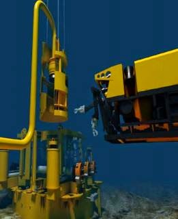
One alternative to insulating marine pipelines and dealing with the thermal expansion problem is to utilize a "pipe-in-pipe" design (Fig. 1).
In this system the inner pipe, known as the "carrier" pipe, carries the crude oil. The carrier pipe is encased in an outer pipe, known as the "jacket."
The annulus between the two pipes is filled with insulation, usually a polyurethane foam of relatively low density. The primary function of the jacket pipe is to provide protection for the insulation.
Marine pipeline systems are generally constructed of 40-ft segments of pipe, a constraint usually dictated by the capabilities of the lay vessel. A pipe-in-pipe pipeline consisting of doublepipe construction can be prefabricated, corrosion coated, and weight coated in the pipe yard similar to a standard single-pipe pipeline.
The individual segments can then be welded on the lay barge into a continuous pipeline during pipe lay operation.
(Editor's note: A configuration similar to this one has been developed for Total Oil Marine plc's Dunbar field in the U.K.'s North Sea sector,OGJ, May 17, p. 61.)
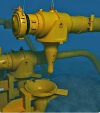
In the pipe-in-pipe design, the jacket pipe and the carrier pipe are connected to each other near the end of each pipe segment by a "donut plate." The jacket pipe and the carrier pipe must be connected to each other at the ends, for the sake of structural stability and water tightness to protect the insulation.
This donut-plate connection becomes the single most important element in the double-walled pipeline system design, when the effect of the thermal loads are considered. Forces generated by the thermal expansion of the carrier pipe are resisted by the donut plates at either end of the pipeline segment.
Management of thermal forces and expansions must be undertaken carefully. Because the two pipes are connected to each other and subjected to different temperatures, each will resist the expansion of the other.
The resulting differential expansions will generate large internal forces in each pipe. While the carrier pipe is subjected to thermal expansion as a result of the hot flowing product, the jacket pipe will not expand because it lies in ambient water temperature.
Stress analysis of the pipe segment must include the jacket pipe, the carrier pipe, and the donut plate as a unit, and is quite complex.
During its thermal expansion, the carrier pipe exerts forces on the donut plates. The donut plates in turn transmit the force to the jacket pipe (Fig. 2).
The nature of the force in the carrier pipe is compressive whereas it is tensile in the jacket pipe. The aspect ratio of the donut plates must be designed so that the force exerted by the carrier pipe is transferred directly to the jacket pipe in shear.
Bending moment is also generated at the inner and outer edges of the donut plates, at the jacket and carrier-pipe joints. The magnitude of this bending stress is controlled by varying the dimensions of the various elements at the joint.
Forces and moments in the donut plate can be calculated with equations derived from plate-bending theory. More sophisticated analysis can also be performed using the finite-element method.
Although the thermal forces can be viewed as a problem by the design engineer, several distinct benefits are derived from this thermally loaded structure.
The expansion of the carrier pipe is restrained at both ends by the donut plates. This restraint induces compressive forces in the carrier pipe and tension in the jacket pipe.
The tension in the jacket pipe leads to an increased allowable free span length of the pipeline and also reduces the overall expansion of the entire pipeline.
Additionally, the resulting tensile force in the jacket pipe adds to the buckling capacity of the jacket pipe. These forces reduce the required jacket pipe wall thickness, leading to substantial material cost savings.
A possible alternative to the pipe-in-pipe segment design is a prefabricated end joint manufactured by third-party suppliers (for example, Snamprogetti of Italy; Fig. 3).
This prefabricated unit is essentially similar to the joint with donut plates. But stress distribution in the prefabricated units is different, and the pipeline segment fabrication requires considerable control of manufacturing tolerances and welding procedures.
The design engineer must keep economics and constructability in perspective when choosing the right fabrication method.

EXPANSION MANAGEMENT

Thermal expansion in marine pipelines cannot be eliminated completely. The pipeline will expand, no matter how small the growth. Restrictions of the expansion of the pipe are confined by allowable stress limitation; of the various components of the pipeline system.
The donut plates described do not restrict the expansion of the carrier pipe entirely. Some expansion is anticipated because the compressive force in the carrier pipe must remain within the critical buckling load, and the combined stresses must also be kept below allowable values.
It is unnecessary to restrict the thermal expansion of the pipeline entirely. The magnitude of thermal expansion allowed in the pipeline system, however, must be managed in such a way that it is safe, economical, and allows uninterrupted operation of the pipeline system.
The following methods are suggested to manage the expansion and resulting stresses in a marine pipeline system.

DOGLEG CONFIGURATION

The "dogleg" configuration (Fig. 4) is useful for managing thermal expansion at the base of a riser, at a PLEM connection, or at any subsea tie-in location.
The total expansion of the pipeline end must equal the allowable horizontal deflection of the dogleg and the allowable torsional deflection of the riser.
Horizontal deflection of the dogleg is determined by application of principles of applied mechanics, as explained previously. The dogleg will deflect as a typical cantilever beam, fixed at the base of the riser.
Deflection of the cantilever is calculated as shown in Equation 4. The torsional deflection is determined by the actual twisting of the riser over a predetermined length. The relationship for the torsional deflection is expressed by Equation 5.
The stresses are optimized in the pipeline segment and the riser by controlling the stiffness of the respective members. The advantage of using this form of connection is that the actual pipe segment can be utilized to take up the thermal expansion. Depending on the required member lengths and allowable space at the base of the riser, this connection offers a simple, efficient method to control thermal expansion.

"U" LOOP

The "U" loop connection combines two "dogleg" configurations set back-to back (Fig. 5). The loop absorbs the thermal expansion of the pipeline by deflecting all three members that constitute the U.
Dimensions of the U-loop can be determined by analyzing it as a frame, subject to displacements at the ends. The magnitude of the displacement at one end is theoretically equal to half the allowed thermal expansion of the pipeline.
The advantage of a U loop over a dogleg design is that generally the loop allows the use of shorter dimensions and in some cases the constructability and installation of the unit are simplified.
In theory this configuration will function as designed so long as the resistance on all of the components is uniform. In a marine environment, where the consistence of the soils cannot be controlled, however, soil resistance on the various components will vary. This variance causes the components to be loaded inconsistently, resulting in unpredictable stress levels.

DYNAMIC CONNECTIONS

With the dogleg and U loop configurations, the thermal expansion of the pipeline is taken primarily as bending stress.
Dynamic balls or joints, such as those manufactured by Cooper Oil Tools, Houston, relieve the thermal expansion by controlled deformation of the joint (Fig. 6). The ball joint stay's dynamic (movable) during its entire design life and allows the pipeline thermal expansions to take place.
These joints are capable of an angular movement of as much as 10 from their centered position while allowing unobstructed flow of the product as well as normal pigging operations.
The most significant advantage of using these joints is the stress-free operation of the pipeline under thermal expansion. Virtually no loads are generated as a result of the thermal expansion of the pipeline when swivel joints are used.
A few of these dynamic joints have been used in marine environments for as long as 20 years and are known to have functioned relatively problem free. Many operators are concerned with leakage integrity and long-term reliability, however, and are not ready to use them extensively.

PRESTRESSED COMPONENTS

Sometimes reduction in thermal stresses and thermal expansions may be achieved by prestressing the pipeline during installation.
This is accomplished by predeflecting a U loop or dogleg configuration equal to the magnitude of the expected expansion, but in the opposite direction. During operation, when the pipeline is heated and expands, the predeflection is dissipated and the pipeline system comes to a virtual stress-free condition.
This alternative is generally feasible where pipeline components expand only in a single direction and seldom return to their original state.
If the prestressed components are allowed to sit too long without subjecting them to thermal loads, however, there will be a gradual redistribution of the preapplied loads, and the intended preload will be negated. This can easily happen should system start-up be delayed after installation.

Source : http://www.ogj.com/articles/print/volume-91/issue-35/in-this-issue/pipeline/design-method-addresses-subsea-pipeline-thermal-stresses.html

Pipeline Hot Tap

What is a Hot Tap?

Hot Taps or Hot Tapping is the ability to safely tie into a pressurized system, by drilling or cutting, while it is on stream and under pressure.
Typical connections consist:
  • Tapping fittings like Weldolet®, Reinforced Branch or Split Tee.
    Split Tees often to be used as branch and main pipe has the same diameters.
  • Isolation Valve like gate or Ball Valve.
  • Hot tapping machine which includes the cutter, and housing.
Mechanical fittings may be used for making hot taps on pipelines and mains provided they are designed for the operating pressure of the pipeline or main, and are suitable for the purpose.
  • Design: ANSI B31.1, B31.3, ANSI B31.4 & B31.8, ASME Sec. VIII Div.1 & 2
  • Fabrication: ASME Sec. VIII Div.1
  • Welding: ASME Sec. IX
  • NDT: ASME Sec. V
There are many reasons to made a Hot Tap. While is preferred to install nozzles during a turnaround, installing a nozzle with equipment in operation is sometimes advantageous, especially if it averts a costly shut down.

Remarks before made a Hot Tap

  • A hot tap shall not be considered a routine procedure, but shall be used only when there is no practical alternative.
  • Hot Taps shall be installed by trained and experienced crews.
  • It should be noted that hot tapping of sour gas lines presents special health and metallurgical concerns and shall be done only to written operating company approved plans.
  • For each hottap shall be ensured that the pipe that is drilled or sawed has sufficient wall thickness, which can be measured with ultrasonic thickness gauges. The existing pipe wall thickness (actual) needs to be at least equal to the required thickness for pressure plus a reasonable thickness allowance for welding. If the actual thickness is barely more than that required for pressure, then loss of containment at the weld pool is a risk.
  • Welding on in-service pipelines requires weld procedure development and qualification, as well as a highly trained workforce to ensure integrity of welds when pipelines are operating at full pressure and under full flow conditions.
Hot Tap fittings

Hot Tap setup

For a hot tap, there are three key components necessary to safely drill into a pipe; the fitting, the Valve, and the hot tap machine. The fitting is attached to the pipe, mostly by welding.
In many cases, the fitting is a Weldolet® where a flange is welded, or a split tee with a flanged outlet (see image above).
Onto this fitting, a Valve is attached, and the hot tap machine is attached to the Valve (see images on the right). For hot taps, new Stud Bolts, gaskets and a new Valve should always be used when that components will become part of the permanent facilities and equipment.
The fitting/Valve combination, is attached to the pipe, and is normally pressure tested. The pressure test is very important, so as to make sure that there are no structural problems with the fitting, and so that there are no leaks in the welds.
The hot tap cutter, is a specialized type of hole saw, with a pilot bit in the middle, mounted inside of a hot tap adapter housing.
The hot tap cutter is attached to a cutter holder, with the pilot bit, and is attached to the working end of the hot tap machine, so that it fits into the inside of the tapping adapter.
The tapping adapter will contain the pressure of the pipe system, while the pipe is being cut, it houses the cutter, and cutter holder, and bolts to the Valve.

Hot Tap operation

The Hot Tap is made in one continuous process, the machine is started, and the cut continues, until the cutter passes through the pipe wall, resulting in the removal of a section of pipe, known as the "coupon".
The coupon is normally retained on one or more u-wires, which are attached to the pilot bit. Once the cutter has cut through the pipe, the hot tap machine is stopped, the cutter is retracted into the hot tap adapter, and the Valve is closed.
Pressure is bled off from the inside of the Tapping Adapter, so that the hot tap machine can be removed from the line. The machine is removed from the line, and the new service is established.


Hot Tap Coupon

The Coupon, is the section of pipe that is removed, to establish service. It is very highly desirable to "retain" the coupon, and remove it from the pipe, and in the vast majority of hot taps, this is the case.
Please note, short of not performing the hot tap, there is no way to absolutely guarantee that the coupon will not be "dropped".
Coupon retention is mostly the "job" of the u-wires. These are wires which run through the pilot bit, and are cut and bent, so that they can fold back against the bit, into a relief area milled into the bit, and then fold out, when the pilot bit has cut through the pipe.
In almost all cases, multiple u-wires are used, to act as insurance against losing the coupon.


Line Stopping

Line Stops, sometimes called Stopples (Stopple® is a trademark of TD Williamson Company) start with a hot tap, but are intended to stop the flow in the pipe.
Line Stops are of necessity, somewhat more complicated than normal hot taps, but they start out in much the same way. A fitting is attached to the pipe, a hot tap is performed as previously detailed. Once the hot tap has been completed, the Valve is closed, then another machine, known as a line stop actuator is installed on the pipe.
The line stop actuator is used to insert a plugging head into the pipe, the most common type being a pivot head mechanism. Line stops are used to replace Valves, fittings and other equipment. Once the job is done, pressure is equalized, and the line stop head is removed.
The Line Stop Fitting has a specially modified flange, which includes a special plug, that allows for removal of the Valve. There are several different designs for these flanges, but they all work pretty much the same, the plug is inserted into the flange through the Valve, it is securely locked in place, with the result that the pressure can be bled off of the housing and Valve, the Valve can then be removed, and the flange blinded off.

Line Stop setup

The Line Stop Setup includes the hot tap machine, plus an additional piece of equipment, a line stop actuator. The Line Stop Actuator can be either mechanical (screw type), or hydraulic, it is used, to place the line stop head into the line, therefore stopping the flow in the line.
The Line Stop Actuator is bolted to a Line Stop Housing, which has to be long enough to include the line stop head (pivot head, or folding head), so that the Line Stop Actuator, and Housing, can be bolted to the line stop Valve.
Line stops often utilize special Valves, called Sandwich Valves.
Line Stops are normally performed through rental Valves, owned by the service company who performs the work, once the work is completed, the fitting will remain on the pipe, but the Valve and all other equipment is removed.

Line Stop operation

A Line Stop starts out the same way as does a Hot Tap, but a larger cutter is used,.
The larger hole in the pipe, allows the line stop head to fit into the pipe.
Once the cut is made, the Valve is closed the hot tap machine is removed from the line, and a line stop actuator is bolted into place.
New gaskets are always to be used for every setup, but "used" studs and nuts are often used, because this operation is a temporary operation, the Valve, machine, and actuator are removed at the end of the job.
New studs, nuts, and gaskets should be used on the final completion, when a blind flange is installed outside of the completion plug.
The line stop actuator is operated, to push the plugging head (line stop head), down, into the pipe, the common pivot head, will pivot in the direction of the flow, and form a stop, thus stopping the flow in the pipe.

Completion Plug

In order to remove the Valve used for line stop operations, a completion plug is set into the line stop fitting flange (Completion Flange).
There are several different types of completion flange/plug sets, but they all operate in basically the same manner, the completion plug and flange are manufactured, so as to allow the flange, to accept and lock into place, a completion plug.
This completion plug is set below the Valve, once set, pressure above the plug can be bled off, and the Valve can then be removed.
Once the plug has been properly positioned, it is locked into place with the lock ring segments, this prevents plug movement, with the o-ring becoming the primary seal.
Several different types of completion plugs have been developed with metal to metal seals, in addition to the o-ring seal.
Line Stopping
Procedure
All following images are from Furmanite.
They are a little matched to the style
of this website requirements.
Line StopLine StopLine StopLine StopLine StopLine Stop
Line StopLine Stop

Line StopLine Stop
Line StopLine Stop
Line StopLine StopLine StopLine Stop
Line Stop

Source :
http://www.wermac.org/specials/hottap.html