Wednesday, February 4, 2015

Pipeline Decommissioning

PIPELINE
Removal
1. Reverse Reeling

For pipelines with a diameter of 16 inches or less, which are not concrete coated, a possible method of removal is by a reversal of the reeling installatin process. Reeling is the installatin method and has been used extensively across the North Sea for both rigid and flexible flowlines.

The installatin of rigid pipelines by the reeling method relies on the plasti deformatin of the pipe wall during installatin to ensure the reeled pipeline will subsequently lie straight on the seabed.  When the process is reversed for the removal of a pipeline, the pipe is reeled onto the specialist reel vessel and is once again plastially deformed so that it sits on the recovery reel. The length of pipeline that can be recovered is limited by the size and capacity of the reel. Once the pipeline is on the reel it is taken to a shore-based facility and removed by reversing the process once again.

Due to the nature of the reeling and unreeling process, it is unlikely that a rigid pipeline recovered using this method could be reused. The multile cycles of plasti deformatin of the pipeline wall could potentially compromise its long term integrity. The steel from recovered rigid pipelines is recycled.
This method is also used in the recovery of flexible flowlines. The structure of the wall of a flexible flowline means it doesn’t experience the same deformatin cycles as the rigid pipeline during the reeling and unreeling process. Multiple reeling and unreeling cycles should not, therefore, compromise the longterm integrity of a flexible flowline. In theory, such pipelines have the potential for reuse if a suitable applicatin is found. It is,however, the responsibility of the end-user to demonstrate the integrity of a recovered flowline.
Reeling vessel

2. Reverse S-lay
Larger diameter and concrete coated trunklines are typically installed using the S-lay method. Although it has never been used before in the North Sea, a potentil removal method is the reversal of the S-lay installatin process. This method is oftn considered in the CA (Comparatie Assessment) for decommissioning pipelines in excess of 16 inches diameter and/or concrete coated.

This method would involve recovering a pipeline end to the deck of a specialist S-lay vessel. The vessel would then move along the route of the pipeline, stopping at suitable points where a cut would be made to remove a section of pipe from the recovered pipeline string on the deck of the vessel. These sections would then be transferred to a suitable transportation barge for onshore recycling.

Although there have been some examples of the application of this method in the shallow water (less than 24 metres water depth) of the Gulf of Mexico, a number of signifiant technical limitations currently exist which preclude its large scale applicatin, i.e.:
o   High tension forces would need to be applied to the pipeline during recovery from the vessel tensioner system to the outer surface of the concrete weight coat to bring the pipe onto the deck and hold it in place for cuttingng. The integrity of aged concrete weight coating cannot be assured and would need to be carefully assessed to confim that the necessary tension could be generated, without the concrete coating disintegrating and the control of the pipeline being compromised.
o   This tension would also be applied into the steel wall of the pipeline and after many years of operation, the integrity of the pipe wall along its length under the high recovery loads would need to be confimed.
o   There is the potentil forverylarge quantities of materials to be recovered during the decommissioning of a large diameter trunkline. There is no established supply chain/disposal route for the quantities of concrete, steel and anticorrosion coatings which would be taken onshore during a major pipeline removal campaign.

Pipelay vessel
3. Cut and Lift
Another possible method used for the removal of pipeline sections is the so-called ‘cut and lift method. This can be used for any diameter or length of pipeline. This is the process whereby a pipeline is cut into sections subsea by diver-operated cutting tools or using remotely operated cutting equipment, and the sections are then recovered to a surface vessel using an on-board crane.

This option has been widely used for removing shorter sections of pipe, either for the removal of a short pipeline in its entirety, or when discrete sections are being removed under a decommissioning plan. It is usually the preferred removal option for short sections of pipe, when it is impractial or prohibitively expensive to mobilise major removal equipment.

Most signifiantly, the cut and lift method does create greater risks to the personnel carrying out the offshore option, especially divers. It has therefore been preferable to limit that risk exposure by avoiding extensive offhore cut and lift programmes.

Recycling
When lengths or sections of steel rigid pipelines are recovered as part of a decommissioning programme, the steel itself is recycled using a proven supply chain. All steel pipelines have an anticorrosion coating and often have insulatin coatigs applied. Where possible these coatigs are removed and recycled, otherwise they are sent to landfil.
For recovered flexible flowlines, umbilicals and power cables, the metallic end fittings can be removed and recycled, or in some instances reused. The metallic elements of the carcass of flexible flowlines, and the wires used in armouring layers in umbilicals and power cables, can also be recovered using specialist equipment and then recycled. Such processes separate out the plastic materials from the different layers, which can then be recycled if possible.
A decommissioning project typically achieves recycling or reuse rates in excess of 95 percent of the recovered materials, and in some cases up to 98 percent. Similar rates can be achieved for pipeline decommissioning projects, depending on the volume and type of non-recyclable coatings recovered with the pipelines.

Reuse
Integrity is a key issue when considering the reuse of pipelines or pipeline materials. For rigid steel pipelines, recovered in a single length by the reverse reeling process, the pipe wall will have been subject to significant reverse cycle plastic deformatin during its original deployment and then recovery process. This can signifiantly affect the long term integrity of the pipe structure and would rule it out for reuse. Hence, no steel pipeline recovered in this way has been reused.

It would be possible to demonstrate that a decommissioned pipeline left in situ could be reused for alternatie service and operating conditions and this is regularly considered.

Flexible flowlines, umbilicals and power cables are readily recovered by reverse reeling as part of a decommissioning programme. Such materials can theoretically be reused, but proving that the integrity of the complex multilayered structure of such components has not been compromised during the handling and operational process is difficult, and often recycling is the only realistic option.

ANCILLARY EQUIPMENT
Mattresses
The DECC guidance on mattesses and grout bags is that they should be removed from the seabed at decommissioning. The guidance does, however, recognise that in some circumstances it might be better for badly degraded mattesses to be decommissioned in situ. In such circumstances, a CA is required to demonstrate that the best decommissioning option has been chosen. It is common practie to remove mattesses and grout bags during the decommissioning ofa pipeline and associated ti-ins, without a  separate CA being performed.
The feasibility ofremoval depends mainly on the age ofthe mattess, and its burial status. Bitumen mattresses can be diffilt to recover as they can break up when liftd. Similarly, older block-type mattesses can disintegrate during recovery due to the degradatin of the polypropylene rope holding the blocks together. In such circumstances, the risk to personnel performing the decommissioning increases and the operator may request permission to decommission such mattesses in situ.
Some mattesses are fitd with fronds to promote sediment depositin aftr deployment. These, and other mattesses, can become buried over tie, and under such circumstances the operator could request that they are decommissioned in situ.

Crossings, Grout Bags and Concrete Formwork

If a pipeline being decommissioned crosses other operatinal pipelines, it is usual practie to leave the constructed crossing in place unti all pipelines are decommissioned. This avoids unnecessary risks to the ‘live’ infrastructure. This represents a deferral of the decommissioning works.

As for all pipeline infrastructure, operators are required to considerall options fordecommissioning a crossing. Any proposal to leave all or part of a crossing in situ must be supported with evidence demonstratig the reasons why this is preferred. Such reasons may include suffient burial, impractialitis or safety concerns with removal, or any other exceptinal circumstance. Many crossings are rock dumped for protectin, which may be a valid reason why the crossing should be lef in situ.
Formwork used to construct larger crossings is installed using dedicated liftng pad-eyes or slings, built into the concrete structure. The feasibility of removing such items by reversing this process requires confimation of the integrity of the lif points. Under such circumstances it may be demonstrated that decommissioning in situ is preferred.

Source:
Unknown, Decommissioning of Pipelines in the North Sea Region 2013, Oil and Gas UK

Pipeline Material Selection

Originally written by Krupavaram Nalli, Tebodin & Partners LLC, Sultanate of Oman
With the recent spate of material failures in the oil and gas industry around the world, the role of a material and corrosion engineer in selecting suitable material has become more complex, controversial and difficult. Further, the task had become more diverse, since now modern engineering materials offer a wide spectrum of attractive properties and viable benefits.
From the earlier years or late ’70s, the process of materials selection that had been confined exclusively to a material engineer, a metallurgist or a corrosion specialist has widened today to encompass other disciplines like process, operations, integrity, etc. Material selection is no more under a single umbrella but has become an integrated team effort and a multidisciplinary approach. The material or corrosion specialist in today’s environment has to play the role of negotiator or mediator between the conflicting interests of other peer disciplines like process, operations, concept, finance, budgeting, etc.
With this as backdrop, this article presents various stages in the material selection process and offers a rational path for the selection process toward a distinctive, focused and structured holistic approach.
What is material selection in oil and gas industry? Material selection in the oil and gas industry - by and large - is the process of short listing technically suitable material options and materials for an intended application. Further to these options, it is the process of selecting the most cost- effective material option for the specified operating life of the asset, bearing in mind the health, safety and environmental aspects and sustainable development of the asset, technical integrity and any asset operational constraints envisaged in the operating life of the asset.
What stages are involved? The stages involved in the material selection process can be outlined as material selection 1) during the concept or basic engineering stage, 2) during the detailed engineering stage, and 3) for failure prevention (lessons learned).

Concept Stage

Material selection during the concept stage basically means the investigative approach for the various available material options for the intended function and application. In this stage, a key factor for the material selection is an up-front activity taking into consideration operational flexibility, cost, availability or sourcing and, finally, the performance of the material for the intended service and application.
The material and corrosion engineer’s specialized expertise or skills become more important as the application becomes critical, such as highly sour conditions, highly corrosive and aggressive fluids, high temperatures and highly stressed environments, etc.
It is imperative at this concept stage that the material selection process becomes an interdisciplinary team approach rather an individualistic material and corrosion engineer’s choice. However, some level of material selection must be made in order to proceed with the detailed design activities or engineering phase.
The number and availability of material options in today’s industry have grown tremendously and have made the selection process more intricate than a few decades back. The trend with research and development in the materials sciences will continue to grow and may make the selection even more complex and intriguing.
It should be understood that, at the concept design stage, the selection is broad and wide. This stage defines the options available for specific application with the available family of materials like metals, non metals, composites, plastics, etc. If an innovative and cost-effective material choice is to be made from an available family of options, it is normally done at this stage.
At times, material constraints from the client or operating company or the end user may dictate the material selections as part of a contractual obligation. Sourcing, financial and cost constraints at times may also limit and obstruct the material selections except for vey critical applications where the properties and technical acceptability of the material is more assertive and outweighs the cost of the material.
Materials availability is another important criterion on the material selection which impacts the demanding project schedules for the technically suitable material options. Also, different engineering disciplines may have different and specific requirements like constructability, maintainability, etc. However, a compromise shall be reached at this stage among all the disciplines concerned to arrive at a viable economic compromise on the candidate material.


Detailed Engineering Stage

Materials selection during the detailed design stage becomes more focused and specific. The material selection process narrows down to a small group or family of materials, say: carbon steels, stainless steels, duplex stainless steels, Inconels or Incoloys, etc. In the detail design stage, it narrows down to a single material and other conditions of supply like Austenitic stainless steels, Martensitic stainless steels, cast materials, forged materials, etc.
Depending on the criticality of the application at this stage the material properties, manufacturing processes and quality requirements will be addressed to more precise levels and details. This may sometimes involve extensive material-testing programs for corrosion, high temperature, and simulated heat treatment as well as proof testing.
From the concept to detailing stage is a progressive process ranging from larger broad possibilities to screening to a specific material and supply condition.
At times, the selection activity may involve a totally new project (greenfield) or to an extension of existing project (brownfield). In the case of an existing project, it could be necessary to check and evaluate the adequacy of the current materials; it may be necessary at times to select a material with enhanced properties. The candidate material shall normally be investigated for more details in terms of cost, performance, fabricability, availability and any requirements of additional testing in the detail engineering stage.

Failure Prevention (Lessons Learned)

Material selection and the sustainability of material to prevent any failure during the life of the component is the final selection criterion in the process.
Failure is defined as an event where the material or the component did not accomplish the intended function or application. In most cases, the material failure is attributed to the selection of the wrong material for the particular application. Hence, the review and analysis of the failure is a very important aspect in the material selection process to avert any similar failures of the material in future.
The failure analysis - or the lessons learned - may not always result in better material. The analysis may, at times, study and consider the steps to reduce the impact on the factors that caused the failure. A typical example would be to introduce a chemical inhibition system into the process to mitigate corrosion of the material or to carry out a post-weld heat treatment to minimize the residual stresses in the material which has led to stress corrosion cracking failure.
An exhaustive review and study of the existing material that failed, including inadequacy checks and a review of quality levels imposed on the failed materials, is required before an alternate and different material is selected for the application.
The importance of the failure analysis cannot be overstressed in view of the spate of failures in recent times in the oil and gas industry. The results of failure analysis and study will provide valuable information to guide the material selection process and can serve as input for the recommendation in the concept and design stages of the project. It strengthens and reinforces the material selection process with sound back-up information.
Let us take a general view of material recommendations for pipelines. Some of the materials most relevant for use in pipelines in the Middle East are indicated for information and guidance in Table 1. The recommendations are general in nature and each pipeline is to be studied in detail case by case as regards operating conditions, fluid compositions, etc. before any final selections.
Also, other considerations - like the total length of the pipeline, above or below ground installation, nature of the pipeline (export line or processing line, etc.) – that are to be taken into consideration during the detailed engineering phase.
Table 1: General Material Selection for Pipelines in Oil and Gas Industry.
materialchart
Notes: CA: Corrosion Allowance, CS: Carbon Steel, CRA: Corrosion Resistant Alloy and GRP: Glass Reinforced Plastics. The recommendations in Table 1 are for guidance only. Each pipeline is to be analyzed on a case-by-case basis based on operating conditions and fluid compositions.


Conclusion

To maintain the integrity of the asset and provide a safe, healthful working environment it is always a welcome event to have the material selection process be executed as a holistic team approach rather than an individual metallurgist’s or corrosion specialist’s choice.

Reference:

Linepipe Manufacture

Line pipe (segmen pipa) terbuat dari lempengan baja yang dibengkokkan lalu dilas pada ujungnya sehingga membentuk tabung. Pengelasan (welding) lempengan baja ini dapat dilakukan dengan beberapa cara, diantaranya adalah dengan metode lap welding, electric resistance welded (ERW), double submerged arc welded (DSAW), spiral welded, atau dapat juga dibuat tanpa adanya pengelasan (seamless pipe).
 

Seamless pipe (kiri) dan spiral welded pipe (kanan)
Kemudian, lapisan luar pipa baja tersebut dilapisi dengan lapisan anti korosi. Jenis serta banyaknya lapisan anti korosi yang digunakan ditentukan berdasarkan kebutuhan dan kondisi lingkungan. Di bawah ini merupakan contoh lapisan anti korosi yang digunakan untuk melapisi line pipe.

Ilustrasi contoh lapisan pelindung anti korosi
Selain itu, line pipe juga diberi selimut beton yang berguna untuk menambah massa pipa yang berfungsi untuk meningkatkan kestabilan pipa di dasar laut dan terkadang juga ditambahi kerangka luar yang berfungsi untuk mencegah keretakan saat instalasi. Selimut beton tidak sepenuhnya menutupi pipa baja. Pada tiap ujung pipa dibiarkan kosong sebagai tempat untuk mengelas. Pipa hasil produksi ini disebut dengan line pipe yang biasanya berukuran panjang 12 meter.


 Proses pembengkokan baja menjadi pipa
Pipa baja yang sudah dilapisi selimut beton

Di bawah ini adalah contoh proses produksi line pipe yang di las menggunakan metode ERW.
Ilustrasi produksi line pipe dengan metode pengelasan ERW

Untuk proses coating (pelapisan anti korosi) dapat dilihat pada gambar di bawah.

Ilustrasi pelapisan anti korosi pada line pipe

Setelah diproduksi, selanjutnya line pipe akan dibawa menuju ke lokasi instalasi menggunakan barge. Di barge, dua buah line pipe disambung las membentuk double joint. Selanjutnya double joint ini akan disambung  ke rangkaian pipeline dengan di las.

Setelah proses pengelasan selesai, selanjutnya dilakukan pengecekan untuk mencegah terjadinya kebocoran. Apabila telah dipastikan tidak terdapat kebocoran, selanjutnya pada sambungan yang terbuka dipasang wrapping tape untuk mencegah terjadinya korosi akibat air laut. Kemudian barulah pipeline dapat diletakkan.


Pengelasan pipeline

Pengecekan kebocoran


Pemasangan wraping tape

Ilustrasi perletakan pipeline

Referensi :

Video : National Geographic: Megastructures - Super Pipeline

Pipeline Mechanical Connector

Untuk menghubungkan antar pipeline dan flowline/jumper dengan fasilitas lainnya di bawah air adalah dengan koneksi flange, collet, clamp dan dalam sekala yang lebih kecil mandrel. Pemasangannya bisa dilakukan oleh diver atau secara jarak jauh (remote) oleh ROV.
Ada perbedaan yang mendasar dengan aktifitas yang sama di atas air dalam hal penanganan (material handling), pemotongan, pengepasan, dsb. Selain kalau pemasangan dengan diver, kita perlu pendekatan yang berbeda.

Koneksi vertikal
Koneksi horizontal


Dilihat dari orientasi porch, kita mengenal koneksi vertikal dan horisontal. Gambar di atas ini untuk memberikan ilustrasi dari kedua orientasi ini. Tabel di bawah ini akan mencantumkan perbedaan-perbedaan dari keduanya.

Untuk memasang konektor, baik diver ataupun memakai ROV, ada tiga fasa yang biasanya memerlukan alat yang berbeda: penarikan pipa (pull-in), pengepasan (alignment) dan pengencangan (connection).

Flange
Koneksi flange bisa dilakukan baik dengan cara diving ataupun jarak jauh (remote) dengan ROV.
Kelebihan teknik ini adalah koneksi yang kuat, efisien secara struktural dan biasa digunakan untuk kondisi yang berat. Koneksi flange juga relatif lebih mudah untuk diinsulasi dibandingkan dengan jenis koneksi lain yang berbentuk ‘janggal’.

Ada dua jenis produk flange ini: standar(API/ANSI) dan flange kompak. Contoh flange kompak adalah SPO dari Vector, ReFlange dari Oceaneering dan Desflex dari Destec. Koneksi flange oleh diver hanya bisa dilakukan sampai kedalaman tertentu saja. Untuk laut yang lebih dalam, alternatifnya adalah memakai ROV/ROT. Ada beberapa teknologi siap pakai seperti Brutus dari Sonsub dan Matis dari Stolt (sekarang Acergy). Brutus bisa dipakai untuk koneksi baik pipa rigid maupun fleksibel tapi hanya bisa dipakai untuk koneksi horisontal saja mencakup flange standar API, ANSI dan compact flange. Brutus bisa bekerja untuk pipa berukuran sampai dengan 24 inci diameter di kedalaman 3000m.
Brutus
MATIS (Modular Advanced Tie-In System) dirancang untuk bias beroperasi untuk koneksi horizontal dan vertikal. Matis bisa dipakai untuk flange dengan standard API dan ANSI, bisa dipakai sampai dengan ukuran pipa 36 inci diameter.
Untuk laut dalam (sampai kedalaman 3000m) ada Deep Matis. Cuma ukuran pipa maksimum yang bisa disambung 12 inci.
Matis

Collect
Konektor jenis ini adalah alternatif yang paling mahal dan kompleks dibanding yang lainnya. Konektor collet terdiri dari ‘jari-jari’ yang dengan kuat akan memegang hub lawannya (lihat gambar) dengan bantuan tekanan hidrolik dan drive ring, jari-jari tersebut akan dikunci. Konektor ini bias dipakai untuk pipa yang rigid atau fleksibel juga untuk konfigurasi vertikal atau horisontal. Konektor ini banyak dipakai di seluruh dunia. Waktu koneksinya cukup singkat.
Konektor Collect dari Cameron
Ada dua jenis collet: integral dan non-integral. Collet integral mempunyai penggerak sendiri dalam badanya sehingga bentuknya lebih besar. Collet non-integral karena harus digerakan dari luar, bentuknya jadi lebih kecil. Untuk melakukan penyambungan dengan konektor ini, ada beberapa sistem yang bias dipakai. FMC memproduksi KC Connector. Oilstates HydroTec juga memproduksinya dengan merek dagang Collet Connector dan Cameron memproduksi CVC. Secara umum, maksimum diameter pipa yang bisa memakai teknologi ini adalah 42 inci sampai kedalaman sekitar 1600m.

Clamp
Konektor clamp ini cukup kompak dan banyak digunakan untuk penyambungan di laut dalam. Teknologi ini memakai dua buah hub dari masing-masing sisinya lalu disatukan oleh modul berengsel dengan satu, dua atau empat buah baut. Di antara dua hub ini, sebuah ring seal diperlukan untuk gasket.

Konektor ini yang paling ringan di antara yang lainnya dan perlu waktu penyambungan yang singkat juga. Beberapa jenis bisa mengakomodasi kesalahan ukur sampai kira-kira 50. Contoh produk yang ada di pasar adalah Grayloc dari Oceaneering, GSR dari VetcoGray, Techlok/Optima dari Vector, G-Range dari Destec, dan sebagainya.
Koneksi clamp

Untuk memasang clamp beberapa alat ROV tersedia di pasaran, contohnya DMaC dari Intec, RAC dari Big Inch, BBRTS dari Kvaerner dan UTIS dari FMC.

Mandrel
Konektor mandrel banyak digunakan untuk koneksi di sekitar sumur, seperti menyambungkan drilling riser ke BOP stack dan subsea completion juga banyak digunakan untuk riser. Dalam skala yang lebih kecil mulai dipakai untuk menyambungkan flowline. VetcoGray dan Drill-Quip adalah perusahaan yang memproduksi konektor mandrel.

Koneksi mandrel

Tuesday, February 3, 2015

Pipeline Pigging

While buildup in a pipeline can cause transmittal slows or even plugging of the pipeline, cracks or flaws in the line can be disastrous. A form of flow assurance for oil and gas pipelines and flowlines, pipeline pigging ensures the line is running smoothly.

The maintenance tool, pipeline pigs are introduced into the line via a pig trap, which includes a launcher and receiver. Without interrupting flow, the pig is then forced through it by product flow, or it can be towed by another device or cable. Usually cylindrical or spherical, pigs sweep the line by scraping the sides of the pipeline and pushing debris ahead. As the travel along the pipeline, there are a number functions the pig can perform, from clearing the line to inspecting the interior.

Illustrastion of pigging


Pig Foam

There are two main hypotheses for why the process is called "pipeline pigging," although neither have been proved. One theory is that "pig" stands for Pipeline Intervention Gadget. The other states that a leather-bound pig was being sent through the pipeline, and while it passed, the leather squeaked against the sides of the pipe, sounding like a squealing pig.
Engineers must consider a number of criteria when selecting the proper pig for a pipeline. First, it's important to define what task the pig will be performing. Also, size and operating conditions are important to regard. Finally, pipeline layout is integral to consider when choosing a pig.

Because every pipeline is different, there is not a set schedule for pigging a line, although the quantity of debris collected in a pipeline and the amount of wear and tear on it can increase the frequency of pigging. Today, pipeline pigging is used during all phases of the life of a pipeline.

Types Of Pipeline Pigs

Although first used simply to clear the line, the purpose of pipeline pigging has evolved with the development of technologies. Utility pigs are inserted into the pipeline to remove unwanted materials, such as wax, from the line. Inline inspection pigs can also be used to examine the pipeline from the inside, and specialty pigs are used to plug the line or isolate certain areas of the line. Lastly, gel pigs are a liquid chemical pigging system.

Similar to cleaning your plumbing line, utility pigs are used to clean the pipeline of debris or seal the line. Debris can accumulate during construction, and the pipeline is pigged before production commences. Also, debris can build up on the pipeline, and the utility pig is used to scrape it away. Additionally, sealing pigs are used to remove liquids from the pipeline, as well as serve as an interface between two different products within a pipeline. Types of utility pigs include mandrel pigs, foam pigs, solid cast pigs and spherical pigs.

Inspection pigs, also referred to as in-line inspection pigs or smart pigs, gather information about the pipeline from within. . The type of information gathered by smart pigs includes the pipeline diameter, curvature, bends, temperature and pressure, as well as corrosion or metal loss. Inspection pigs utilize two methods to gather information about the interior condition of the pipeline: magnetic flux leakage (MFL) and ultrasonics (UT). MFL inspects the pipeline by sending magnetic flux into the walls of the pipe, detecting leakage, corrosion, or flaws in the pipeline. Ultrasonic inspection directly measures the thickness of the pipe wall by using ultrasonic sounds to measure the amount of time it takes an echo to return to the sensor

Specialty pigs, such as plugs, are used to isolate a section of the pipeline for maintenance work to be performed. The pig plug keeps the pipeline pressure in the line by stopping up the pipeline on either side of where the remedial work is being done.
A combination of gelled liquids, gel pigs can be used in conjunction with conventional pigs or by themselves. Pumped through the pipeline, there are a number of uses for gel pigs, including product separation, debris removal, hydrotesting, dewatering and condensate removal, as well as removing a stuck pig.

Because there now exist multi-diameter pipelines, dual and multi-diameter pigs have been developed, as well.

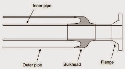
Pipe in Pipe

Pipe in pipe is another insulation method which an inner pipe is covered by a larger outer pipe. The annuals between inner pipe an the outer are filled with insulation materials such as micro-porous silica (aerogel), polyurethane foam (PUF), wacker, mineral wool, etc.

Pipe in pipe section

Pipe in pipe is another insulation method which an inner pipe is covered by a larger outer pipe. The annuals between inner pipe an the outer are filled with insulation materials such as micro-porous silica (aerogel), polyurethane foam (PUF), wacker, mineral wool, etc.

End Bulkhead

Water stops are installed to limit the pipeline length damaged in the event that the annulus is flooded by pipeline failure or puncture. Water stops are not design code requirement but they are recommended for deepwater project whaere recovery of the flooded pipeline is challenging. EPDM or ethylene propylene diene monomer rubber, viton, and sillicone rubber have been used for the water stop material. The axial compression for the water stop is provided by using an interlocking clamp arrangement whic will provide the radial expansion of the ring against the pipe walls.
Water Stop Seal

Centralizers or spacers are polymeric rings clamped on the inner pipe for reeled PIP to protect insulation’s abrasioan damage during insertion of the ineer pipe into the outer pipe, to protect insulation’s crushing due to bending load while reeling, and to protect insulation’s crushing due to thermal buckling during operation.
Centralizer works as a heat sink due to its high thermal conductivity. Therefore, reducing the number of centralizers by increasing the centralizer spacing, or centralizer-less design can reduce both the material and fabrication/installation costs. You can see the figure below to know the shape of centralizer.
Centralizer
For the reeled PIP, the annulus gap needs to be sufficient to put insulation material, centralizer, and clearance gap to account for the weld beads, welding misalignment, pipe manufacturing tolerances, etc. The annulus gap should be in the range of 30 to 40 mm and the net gap (between insulation and outer pipe) should be 15 mm or higher. You can see the figure below to know the what I’ve describe above.

Reeled PIP with centralizer

Reference :
Jaeyoung, Lee. Introduction to Offshore Pipelines and Risers. 2007

Pipeline End Manifold (PLEM)

Ada beberapa jenis FTA (Flowline Termination Assembly) untuk menyambung pipeline dengan fasilitas lainnya, yaitu PLET, PLEM dan Riser Base.

PLET (Pipeline End Termination, gambar kiri) adalah sebuah perangkat keras yang dipasang dikedua ujung pipeline dan dilengkapi dengan porch untuk sistem koneksi tertentu sehingga memungkinkan untuk dihubungkan dengan fasilitas subsea lainnya seperti manifold atau riser end termination (RET). Beberapa PLET ada yang dilengkapi dengan valve untuk mengisolasi aliran sewaktu-waktu diperlukan. PLET di-anchor ke dasar laut bisa dengan gravity base atau struktur yang di-pile tapi mempunyai rail/sled untuk memungkinkan pipa berekspansi.


FTA yang mempunyai hub porch lebih dari satu sehingga bisa mengakomodasi beberapa sambungan disebut PLEM (Pipeline End Manifold, gambar kanan). Riser Base (gambar tengah) adalah termination assembly untuk pipeline dan riser yang merupakan modul tersendiri. Riser base ini harus dipasang tersendiri sehingga butuh dua konektor untuk menghubungkan riser dan pipeline.

PLET, Riser Baser dan PLEM

Manifold subsea merupakan interface antara pipeline atau riser, flowline/jumper dan sumur. Manifold mempunyai fungsi mengumpulkan hasil produksi dari masing-masing sumur untuk didistribusikan ke tempat selanjutnya. Manifold juga mendistribusikan chemical, kontrol fluida, suplay electrik dan hidrolik.

Manifold subsea juga biasanya mempunyai fasilitas untuk pigging (pigging loop atau pig diverter). Pigging loop ini memungkinkan pipeline dan riser untuk dipig tanpa fasilitas subsea pig launcher/receiver.
PLEM


Piping dalam integral manifold 
Fasilitas test, gas lift dan water injection juga secara umum melewati manifold yang sama. Kadang-kadang manifold ini dilengkapi dengan multiphase flowmeter yang bisa dipakai untuk welltest setiap sumur dan/atau untuk total produksi. Secara lokasi, manifold ini ada dua jenis: template manifold dan cluster manifold, lihat juga konfigurasi sumur. Pada template manifold, manifold letaknya jadi satu dengan sumur sedangkan lokasi cluster manifold ada diluar lokasi sumur. Secara struktur, juga ada dua jenis yaitu : integral manifold yang merupakan satu struktur yang menyatu dan retrievable manifold yang terdiri dari beberapa modul yang bisa diambil lagi ke atas air secara terpisah. Dari manifold ini, pengiriman ke stasiun penerima bisa lewat pipeline atau langsung ke riser.

Metode instalasi manifold terbagi kedalam dua: konvensional untuk kedalaman laut sampai 1000m dan non-konvensional untuk kedalaman laut lebih dari 1000m. Metode konvensional adalah metode pengangkatan biasa dengan satu crane dari anchor handler atau barge dengan memakai wire rope atau dari drilling rig dengan menggunakan drilling riser. Metode non-konvensional mengenal sheave dan pendular installation. Kedua metode tersebut menggunakan dua kapal.

Referensi :
Suyanto, Ato (2008), Buku Pintar Migas Indonesia : Teknologi dan Instalasi Subsea Edisi 1